We will use Velero to perform full or partial backup and restore of the cluster and will use Minio to provide a local S3 storage areas on another computer on the network (I just used my Mac laptop, but you could use a server or multiple servers instead), to be able to do scheduled backups with Velero.
Minio
On the Mac, you can use brew to install Minio and the Minio client (mc):
Create an area for data storage and an area for Minio:
cd ~/workspace/picluster
poetry shell
cd mkdir -p ~/workspace/minio-data
mkdir -p ~/workspace/picluster/minio
In the ~/workspace/picluster/minio/minio.cfg create this file with the user/password desired(default is minioadmin/minioadmin) and host name (or IP) where server will run (in this example, I use my laptop name):
# MINIO_ROOT_USER and MINIO_ROOT_PASSWORD sets the root account for the MinIO server.
# This user has unrestricted permissions to perform S3 and administrative API operations on any resource in the deployment.
# Omit to use the default values 'minioadmin:minioadmin'.
# MinIO recommends setting non-default values as a best practice, regardless of environment

MINIO_ROOT_USER=minime
MINIO_ROOT_PASSWORD=PASSWORD_YOU_WANT_HERE

# MINIO_VOLUMES sets the storage volume or path to use for the MinIO server.

MINIO_VOLUMES="~/workspace/minio-data"

# MINIO_SERVER_URL sets the hostname of the local machine for use with the MinIO Server
# MinIO assumes your network control plane can correctly resolve this hostname to the local machine

# Uncomment the following line and replace the value with the correct hostname for the local machine and port for the MinIO server (9000 by default).

MINIO_SERVER_URL="http://triunity.home:9000"
Note: There is no way to change the user/password, from the console later.
Create a minio-credentials file with the same user name and password as was done in the minio.cfg file:
[default]
aws_access_key_id = minime
aws_secret_access_key = SAME_PASSWORD_AS_ABOVE
I did “chmod 700” for both minio.cfg and minio-credentials.
Next, create a script(minio-server-start) to start up Minio with the desired settings:
export MINIO_CONFIG_ENV_FILE=./minio.cfg
minio server --console-address :9090 &
When you run this script, it will output will indicate a warning that the local host has all the data and a failure will cause loss of data (duh). It will show the URL for API (port 9000) and console (port 9090), along with the username and password to access. Near the bottom, it will show you an alias command that you should copy and paste. It names the server and provides credentials info. It looks like:
mc alias set 'myminio' 'http://trinity.home:9000' 'minime' 'THE_PASSWORD_FROM CONFIG'
Then do the following to make sure that the server is running the latest code:
mc admin update myminio
In your browser, go to the URL and log in with the username/password. Under Administrator -> Buckets menu on the left panel, create a bucket called “kubernetes”. I haven’t tried, but you can turn on versioning, object locking, and quota.
For the Mac, use brew to install Velero and either note the version or check with the list command (in my case it has 1.12.3):
brew install velero
brew list velero
You can check compatibility of the Velero version you have and the kubernetes version running (and adjust the version used by brew, if needed). The matrix is here. (Optionally) Pull the Velero sources from git, so that we can use examples and have documentation:
cd ~/workspace/picluster
git clone https://github.com/vmware-tanzu/velero.git
cd velero
In the README.md, it will have version compatibility info.
It indicates that velero 1.12.x works with Kubernetes 1.27.3 and 1.13.x with Kubernetes 1.28.3. We have 1.28 Kubernetes, but there is no brew version for Velero 1.13 right now, so we’ll hope 1.12.3 Velero works.
We need the Velero plugin for AWS. The plugins are shown here. For Velero 1.12.x, we need AWS plugin 1.8.x. The plugin tags show that v1.8.2 is the latest.
Next, start up Velero, specifying the plugin version to use, the bucket name you created in Minio (“kubernetes”), the credentials file, Minio as the S3 storage, and the Minio API URL (your host name with port 9000):
It will display that Velero is installed and that you can use “kubectl logs deployment/velero -n velero” to see the status.
Check that the backup location is available with:
velero backup-location get
NAME      PROVIDER   BUCKET/PREFIX   PHASE       LAST VALIDATED                  ACCESS MODE   DEFAULT
default   aws        kubernetes      Available   2024-01-16 13:15:52 -0500 EST   ReadWrite     true
If you have the Velero git repo pulled, as mentioned above, you can start an example:
cd ~/workspace/picluster/velero
kubectl apply -f examples/nginx-app/base.yaml

kubectl get all -n nginx-example
NAME                                    READY   STATUS    RESTARTS   AGE
pod/nginx-deployment-75b696dc55-25d6r   1/1     Running   0          66s
pod/nginx-deployment-75b696dc55-7h5zx   1/1     Running   0          66s

NAME               TYPE           CLUSTER-IP     EXTERNAL-IP   PORT(S)        AGE
service/my-nginx   LoadBalancer   10.233.46.15   <pending>     80:30270/TCP   66s

NAME                               READY   UP-TO-DATE   AVAILABLE   AGE
deployment.apps/nginx-deployment   2/2     2            2           66s

NAME                                          DESIRED   CURRENT   READY   AGE
replicaset.apps/nginx-deployment-75b696dc55   2         2         2       66s
You should see the deployment running (Note: there is no external IP, as I don’t have a load balancer running right now). If you want to just backup this application, you can do:
velero backup create nginx-backup --selector app=nginx
velero backup get
NAME           STATUS      ERRORS   WARNINGS   CREATED                         EXPIRES   STORAGE LOCATION   SELECTOR
nginx-backup   Completed   0        0          2024-01-16 13:22:53 -0500 EST   29d       default            app=nginx

velero backup describe nginx-backup
velero backup logs nginx-backup
If you look at the “kubernetes” bucket from the Minio console, you’ll see the backup files there. Now, we can delete the application and then restore it…
kubectl delete namespace nginx-example
kubectl get all -n nginx-example
No resources found in nginx-example namespace.

velero restore create --from-backup nginx-backup
Restore request "nginx-backup-20240116132642" submitted successfully.
Run `velero restore describe nginx-backup-20240116132642` or `velero restore logs nginx-backup-20240116132642` for more details.
(picluster-py3.11) pcm@trinity:~/workspace/picluster/velero$ kubectl get all -n nginx-example
NAME                                    READY   STATUS    RESTARTS   AGE
pod/nginx-deployment-75b696dc55-25d6r   1/1     Running   0          3s
pod/nginx-deployment-75b696dc55-7h5zx   1/1     Running   0          3s

NAME               TYPE           CLUSTER-IP      EXTERNAL-IP   PORT(S)        AGE
service/my-nginx   LoadBalancer   10.233.16.165   <pending>     80:31834/TCP   3s

NAME                               READY   UP-TO-DATE   AVAILABLE   AGE
deployment.apps/nginx-deployment   2/2     2            2           2s

NAME                                          DESIRED   CURRENT   READY   AGE
replicaset.apps/nginx-deployment-75b696dc55   2         2         2       3s
You can backup the full cluster with “velero backup create FULL_BACKUP-2024-01-17”, using a name to denote the backup. You can use “velero backup get” to see a list of backups, and “velero restore get” to see a list of restores. You can even schedule backups with a command, like the following:
Lastly, you can delete the “kubernetes” bucket from the Minio console, and kill the Minio process.
Side Bar
I did have a problem at one point (may have been due to an older Minio version), where I deleted a backup from Velero, and it later re-appeared when doing “velero backup get”. I looked at operations with “mc admin trace myminio” and saw that requests were coming into Minio to remove the backup from my “myminio” server, but the bucket was NOT being removed. Velero would later sync with Minio, see the backup and show that it was still there on a later “velero backup get” command.
I found that the following would remove the bucket and everything under:
mc rm --recursive kubernetes --force --dangerous
There is also a “mc rb” command to remove the bucket (have not tried), or an individual backup can be removed with “mc rm RELATIVE/PATH/FROM/BUCKET”, like “kubernetes/backups/nginx-backup” and “kubernetes/restores/nginx-backup-20231205150432”. I think I tried doing it from the Minio UI, but the files were not removed. My guess is that it does an API request to remove the file, just like what Velero does, whereas the command line seems to remove the file.
There are many shared storage products available for Kubernetes. I had settled on Longhorn, as it provides block storage, is pretty easy to setup, has snapshots, is distributed, and allows backup to secondary storage (I plan on using NFS to backup to a NAS box that I have on my network). As of this writing, the latest is 1.5.3 (https://longhorn.io/).
Preparation
With the 1TB SSD drives on each Raspberry PI, and the /dev/sda7 partition, mounted as /var/lib/longhorn, the RPIs can be prepared for Longhorn. There is a script that can be used to see if all the dependencies have been met on the nodes. For 1.5.3 run:
You should make sure that the longhorn-iscsi-installation pods are running on all nodes. In my case, one was not, and the log for the iscsi-installation container was saying that module iscsi_tcp was not present. For that, I did the following:
In my run, I had a node, apoc, with missing package:
[INFO]  Required dependencies 'kubectl jq mktemp sort printf' are installed.
[INFO]  All nodes have unique hostnames.
[INFO]  Waiting for longhorn-environment-check pods to become ready (0/5)...
[INFO]  Waiting for longhorn-environment-check pods to become ready (0/5)...
[INFO]  All longhorn-environment-check pods are ready (5/5).
[INFO]  MountPropagation is enabled
[INFO]  Checking kernel release...
[INFO]  Checking iscsid...
[INFO]  Checking multipathd...
[INFO]  Checking packages...
[ERROR] nfs-common is not found in apoc.
[INFO]  Checking nfs client...
[INFO]  Cleaning up longhorn-environment-check pods...
[INFO]  Cleanup completed.
I did a “sudo apt install nfs-common -y” on that node. Since then, I’ve added that to the RPI tools setup in Part IV, so that it’ll be there. Re-run the script to make sure that all the nodes are ready for install.
Install
Helm has already been installed on my Mac, so we can obtain Longhorn with:
This will allow you to access the UI by using any node’s IP, and when Longhorn is brought down, the files in block storage are retained.
We also need to set tolerations for the manager, UI, and driver. There are instructions in the values.yaml file where you remove the square brackets and un-comment the toleration settings. If you don’t do this, the longhorn-driver-deployment pod will never get out of Init state. Diffs for just the tolerations will look like:
--- a/longhorn/values-1.5.3.yaml
+++ b/longhorn/values-1.5.3.yaml
@@ -182,13 +182,13 @@ longhornManager:
     ## Allowed values are `plain` or `json`.
     format: plain
   priorityClass: ~
-  tolerations: []
+  tolerations:
   ## If you want to set tolerations for Longhorn Manager DaemonSet, delete the `[]` in the line above
   ## and uncomment this example block
-  # - key: "key"
-  #   operator: "Equal"
-  #   value: "value"
-  #   effect: "NoSchedule"
+  - key: "key"
+    operator: "Equal"
+    value: "value"
+    effect: "NoSchedule"
   nodeSelector: {}
   ## If you want to set node selector for Longhorn Manager DaemonSet, delete the `{}` in the line above
   ## and uncomment this example block
@@ -202,13 +202,13 @@ longhornManager:

 longhornDriver:
   priorityClass: ~
-  tolerations: []
+  tolerations:
   ## If you want to set tolerations for Longhorn Driver Deployer Deployment, delete the `[]` in the line above
   ## and uncomment this example block
-  # - key: "key"
-  #   operator: "Equal"
-  #   value: "value"
-  #   effect: "NoSchedule"
+  - key: "key"
+    operator: "Equal"
+    value: "value"
+    effect: "NoSchedule"
   nodeSelector: {}
   ## If you want to set node selector for Longhorn Driver Deployer Deployment, delete the `{}` in the line above
   ## and uncomment this example block
@@ -218,13 +218,13 @@ longhornDriver:
 longhornUI:
   replicas: 2
   priorityClass: ~
-  tolerations: []
+  tolerations:
   ## If you want to set tolerations for Longhorn UI Deployment, delete the `[]` in the line above
   ## and uncomment this example block
-  # - key: "key"
-  #   operator: "Equal"
-  #   value: "value"
-  #   effect: "NoSchedule"
+  - key: "key"
+    operator: "Equal"
+    value: "value"
+    effect: "NoSchedule"
   nodeSelector: {}
   ## If you want to set node selector for Longhorn UI Deployment, delete the `{}` in the line above
   ## and uncomment this example block
Install Longhorn with the updated values and monitor the namespace until you see that everything is up:
helm install longhorn longhorn/longhorn --namespace longhorn-system --create-namespace --version 1.5.3  --values values-1.5.3.yaml
kubectl get all -n longhorn-system
Use “kubectl get service -n longhorn-system” to find the port for the frontend service, and then with a browser you can access the UI using one of the node’s IPs and the port. For example, http://10.11.12.188:30191, on one run that I did.
You can see and manage volumes, view the total amount of disk space and what is scheduled, and see the nodes being used and their state.
Creating Persistent Volume Claim Using Longhorn as Storage
As an example, we can create a PVC that uses Longhorn for storage:
This specifies the PVC “myclaim”, and you can see that there is a PV created that uses the PVC, has reclaim policy of retain, and uses the longhorn storage class:
kubectl get pv
NAME                                       CAPACITY   ACCESS MODES   RECLAIM POLICY   STATUS   CLAIM             STORAGECLASS   REASON   AGE
pvc-89456753-e271-46a0-b8c0-9e53affc4c6b   2Gi        RWX            Retain           Bound    default/myclaim   longhorn                4m35s
Bonus Points
You can setup a backup for the Longhorn storage. In my case, I have a NAS box that is accessible via NFS.
The first step is to create a share area on the device. You can follow whatever instructions youhave for creating a NFS share.
On my NAS (using GUI console), I created a share at /longhorn, with R/W access for my account (I’m in the “administ” group, BTW) and “no squash users” set. I set the IP range to 10.11.12.0/24, so only nodes from network can access this share. I made sure that the shared area exists, has 777 perms, user/group set to admin. NOTE: Is is actually at /share/CACHEDEV1_DATA/longhorn and there is a symlink at /share/longhorn. I created a subdirectory called “backups” in this area (so there can be other sub-directories for other shares, if desired).
I checked that it appears under /etc/exports with the subnet called out and the settings desired:
Under the Longhorn UI (accessible via NodePort), go to Settings, and in the Backup Target, set the path to the NFS share and click the SAVE button at the bottom of the page:
nfs://<IP_OF_NFS_SERVER>:/longhorn/backup/
Once you have created a volume and it is attached to a node, you can do a backup or take a snapshot. Form the Volume section, click on the name of a volume to bring up details, and then you can click on “Take Snapshot” or “Create Backup”. You can go back to older versions of snapshots, by detaching volume and attaching with maintenance checked. From the snapshot, you can check revert and then detach and re-attach w/o maintenance. Once healthy, you can see that the snapshot is there.
Uninstalling
To remove Longhorn, you must set a flag to allow deletion, before removing:
Now that everything is ready, we can use ansible to bring up the cluster with kubespray. The cluster.yml playbook will check to make sure all the dependencies are present on the nodes, versions are correct, and will proceed to install kubernetes on the cluster, as defined by the hosts.yaml you’ve created. Move to the kubespray area, and run the cluster.yaml playbook:
cd ~/workspace/picluster
poetry shell
cd ../kubespray
ansible-playbook -i ../picluster/inventory/mycluster/hosts.yaml -u ${USER} -b -v --private-key=~/.ssh/id_ed25519 cluster.yml
It takes a long time to run, but has a lot to do! With the verbose flag, you can see each step performed and whether or not things were changed or not. At the end, you’ll get a summary, just like on all the other playbooks that were invoked. Here is the end of the output for a run, where I already had a cluster (so things were setup already) and just ran the cluster.yml playbook again.
PLAY RECAP ********************************************************************************************************************************************************************************
cypher                     : ok=658  changed=69   unreachable=0    failed=0    skipped=1123 rescued=0    ignored=0
localhost                  : ok=3    changed=0    unreachable=0    failed=0    skipped=0    rescued=0    ignored=0
lock                       : ok=563  changed=44   unreachable=0    failed=0    skipped=1005 rescued=0    ignored=0
mouse                      : ok=483  changed=50   unreachable=0    failed=0    skipped=717  rescued=0    ignored=0
niobi                      : ok=415  changed=37   unreachable=0    failed=0    skipped=684  rescued=0    ignored=0

Sunday 31 December 2023  10:10:12 -0500 (0:00:00.173)       0:21:31.035 *******
===============================================================================
container-engine/validate-container-engine : Populate service facts --------------------------------------------------------------------------------------------------------------- 99.19s
kubernetes-apps/ansible : Kubernetes Apps | Start Resources ----------------------------------------------------------------------------------------------------------------------- 46.85s
etcd : Reload etcd ---------------------------------------------------------------------------------------------------------------------------------------------------------------- 35.10s
etcd : Gen_certs | Write etcd member/admin and kube_control_plane client certs to other etcd nodes -------------------------------------------------------------------------------- 34.06s
kubespray-defaults : Gather ansible_default_ipv4 from all hosts ------------------------------------------------------------------------------------------------------------------- 27.37s
network_plugin/calico : Start Calico resources ------------------------------------------------------------------------------------------------------------------------------------ 26.65s
download : Download_file | Download item ------------------------------------------------------------------------------------------------------------------------------------------ 25.50s
policy_controller/calico : Start of Calico kube controllers ----------------------------------------------------------------------------------------------------------------------- 17.93s
network_plugin/calico : Check if calico ready ------------------------------------------------------------------------------------------------------------------------------------- 17.34s
kubernetes-apps/ansible : Kubernetes Apps | Lay Down CoreDNS templates ------------------------------------------------------------------------------------------------------------ 17.28s
etcd : Gen_certs | Gather etcd member/admin and kube_control_plane client certs from first etcd node ------------------------------------------------------------------------------ 16.50s
download : Download_file | Download item ------------------------------------------------------------------------------------------------------------------------------------------ 14.33s
download : Check_pull_required |  Generate a list of information about the images on a node --------------------------------------------------------------------------------------- 12.78s
container-engine/containerd : Containerd | restart containerd --------------------------------------------------------------------------------------------------------------------- 12.36s
download : Check_pull_required |  Generate a list of information about the images on a node --------------------------------------------------------------------------------------- 12.13s
etcd : Gen_certs | run cert generation script for etcd and kube control plane nodes ----------------------------------------------------------------------------------------------- 11.75s
download : Check_pull_required |  Generate a list of information about the images on a node --------------------------------------------------------------------------------------- 11.47s
download : Check_pull_required |  Generate a list of information about the images on a node --------------------------------------------------------------------------------------- 11.46s
network_plugin/calico : Calico | Create calico manifests -------------------------------------------------------------------------------------------------------------------------- 11.23s
download : Download_file | Download item ------------------------------------------------------------------------------------------------------------------------------------------ 10.81s
If things are broken, you’ll need to go back and fix them and try again. Once it is working, though, we can now get the kube configuration file, so that we can run kubectl commands (we installed kubectl on the Mac in step IV). I use a script (at ~/workspace/picluster) to make this easy to do:
You’ll need to change the CONTROL_PLANE_NODE with the name of one of the control plane nodes, and CONTROL_PLANE_NODE_IP with that node’s IP address. Once this command is run, the config file will be set up to allow the kubectl command to access the cluster.
Next up in the series will be adding shared storage, a load balancer, ingress, monitoring, etc. Below are some other operations that can be done for the cluster.
Upgrading Cluster
This is a two step process, depending on what version you want to get to with Kubernetes, and what release of kubespray you are running. Each release of kubespray will have a tag and will correspond to a kubernetes version. You can see the tags with:
Alternately, you can just use a specific commit or the latest on the master branch. Once you decide which tag/commit you want, you can do a checkout for that version:
git checkout v2.23.1
git checkout aea150e5d
For whichever tag/commit you use, you can find out the default kubernetes and calico plugin (what I chose for networking), by doing grep commands from the repo area (you can look at specific files, but some times these are stored in different places):
Please note that, with kubespray, you have to upgrade by major release, and cannot skip releases. So, if you want to go from tag v2.21.0 to v2.23.1, you would need to update to v2.22.0 or v2.22.1, and then v2.23.1.0. If you are using a commit, just see what the previous tag was for the commit and then update tags to that tag and then you’ll be all set.
Initially, I ended up using a non-tag version of kubespray because I wanted kubernetes 1.27, and the nearest release tag at the time was v2.22.1, which used kubernetes 1.26.5. I ended up using a commit on master that gave me 1.27.3.
As of this writing, the newest tag is v2.23.1, which is 9 weeks ago, uses kubernetes 1.27.7. I just grabbed the latest on master, which supports kubernetes 1.28.5 (you can see that in commit message):
git show HEAD:inventory/sample/group_vars/k8s_cluster/k8s-cluster.yml | grep kube_version
kube_version: v1.28.5
Granted, you may want to stick to tagged releases (it’s safer), or venture into newer versions, with newer kubernetes. However, you still need to update by a major release at a time with kubespray.
To update kubespray, from ~/workspace/kubernetes/kubespray/ I did the following:
Saved my old inventory: mv ~/workspace/kubernetes/picluster/inventory/mycluster{,.save}
Did a “git pull origin master” for the kubespray repo and checked out the version I wanted (either a tag, latest, etc).
Copied the sample inventory: cp -r inventory/sample ../picluster/inventory/mycluster
Updated files in ../picluster/inventory/mycluster/* from the ones in mycluster.save to get the customizations made. This includes hosts.yaml, group_vars/k8s_cluster/k8s-cluster.yml, group_vars/k8s_cluster/addons.yml, other_servers.yaml, and any other files you customized.
I set the kubernetes_version in group_vars/k8s_cluster/k8s-cluster.yml to the version desired, as this was a customized item that was older.
In my case, the default calico version would be v3.26.4 (before I had v3.25.2 overridden), and kubernetes v1.28.5 (before I had v1.27.3).
Use the following command, to upgrade the cluster, using the new kubespray code and kubernetes version:
When I did this, I ended up with Kubernetes 1.28.2, instead of the default 1.28.5 (not sure why). I ran the upgrade again, only this time I specified “kube_version: v1.28.5” in the ../picluster/inventory/mycluster/group_vars/k8s_cluster/k8s-cluster.yml as an override, but it still was using v1.28.2.
Ref: https://kubespray.io/#/docs/upgrades
Adding a node
I received another Raspberry PI 4 for Christmas and wanted to add it to the cluster. I followed all the steps in Part II to place the Ubuntu on the PI, Part III to repartition the SSD drive, Part IV to add the new host to hosts.yaml and then ran the ansible commands just for the node I was adding to setup the rest of the items needed.
To add a control plane node, update the inventory (adding the node definition, and adding the node name to the control plane list and list of nodes) and run the kubespray cluster.yml script:
To add a worker node, update the inventory (adding the node definition, and adding the node name to the node list) and run the kubespray scale.yml script:
On one attempt, after having updated the kubespray repo to the latest version, the cluster.yaml failed because ansible version I was using was too old:
TASK [Check 2.15.5 <= Ansible version < 2.17.0] *******************************************************************************************************************************************
fatal: [localhost]: FAILED! => {
    "assertion": "ansible_version.string is version(minimal_ansible_version, \">=\")",
    "changed": false,
    "evaluated_to": false,
    "msg": "Ansible must be between 2.15.5 and 2.17.0 exclusive - you have 2.14.13"
}
Doing a “poetry show”, I could see what I had for ansible and one of the dependencies, ansible-core:
ansible          7.6.0   Radically simple IT automation
ansible-core     2.14.13 Radically simple IT automation
To update, I used the command “poetry add ansible@latest”, which would reinstall the latest version and update all the dependencies:
If desired, you can do a “poetry search ansible” or “poetry search ansible-core” to see what the latest version is, and you can always specify exactly which version you want to install. That’s the beauty of poetry, in that you can fix specific versions of a package, so that things are repeatable.
Mismatched Calico/Kubernetes Versions
I had a case where my cluster was at kubernetes v1.27.3 and v3.25.2 Calico. The kubespray repo had a tag of v2.23.1, which called out v1.27.7 kubernetes and v3.25.2 Calico. Things were great.
I tried to update kubespray to latest on master branch, which defaults to kubenetes v1.28.5 and v3.26.4. However, I still had v3.25.2 Calico in my customizations (with kubernetes updated to call out v1.28.5). The cluster.yml playbook ran w/o issues, but the calico-node pods were not up and were in a crash loops. The install-cni container for a calico-node pod was showing an error saying:
Unable to create token for CNI kubeconfig error=serviceaccounts "calico-node" is forbidden: User "system:serviceaccount:kube-system:calico-node" cannot create resource "serviceaccounts/token" in API group "" in the namespace "kube-system"
Even though kubernetes v1.28.5 is supported by Calico v3.25.2, there was some incompatibility. I haven’t figured it out, but I saw this before as well, and the solution was to either use the versions called out in the commit being used for kubespray, or at least near that version for kubernetes. By using the default v3.26.4 Calico, it came up fine.
Also note that even though I specified kubernetes v1.28.5, in my customization (which happened to be the same as the default), I ended up with v1.28.2 (not sure why).
There are a bunch of ways to create a cluster (microk8s, k3s, KOps, kubeadm, kubespray,…) and after looking at a bunch of them, I decided to use kubespray (ref: https://kubespray.io/#/). I’m going to use my MacBook to drive all this, so I setup an environment on that machine with all the tools I needed (and more).
Getting The Provisioning System Ready
I created a directory ~/workspace/picluster to hold everything, and created a git repo so that I have a version controlled area to record all the changes and customizations I’m going to make. For the Mac, I used brew to install python3.11 (ref: https://www.python.org/downloads/) and poetry (ref: https://python-poetry.org/docs/) to create a virtual environment for the tools I use and to fix versions. Currently my poetry environment has:
python is obvious and I’m fixing it to 3.11. ansible is the tool used to provision the nodes. argcomplete is optional, if you want to have command completion. ruamel-yaml is a YAM parser, pbr is used for python builds, netaddr is a network address manipulation lib for python, and jmespath is for JSON matching expression.
You can use any virtual environment tool you want to ensure that you have the desired dependencies. Under “poetry shell“, which creates a virtual environment I continues with the prep work for using kubespray. I installed helm, jq, and kubectl:
Note that, for kubectl, I really wanted v1.28, and specified by version (kubectl@1.28), however, when trying months later, that version appears to not be available, and now it will install 1.29).
Defining Your Inventory
I cloned the kubespray repo and then checked out the version I wanted.
git clone https://github.com/kubernetes-sigs/kubespray.git
git tag | sort -V --reverse
git checkout v2.23.1  # for example
The releases have tags, but you can chose to use any commit desired (or latest). Sometimes, there are newer versions used with commits after the release. For a specific commit, you can see what default Kubernetes version and Calico version are configured for the commit with:
You can override the values in inventory/sample/group_vars/k8s_cluster/k8s-cluster.yml, but make sure the kubernetes and calico versions are compatible. You can check at this Tigera link to see the kubernetes versions supported for a Calico release. I have run into some issues when trying a Calico/Kubernetes pair that was not called out in the kubespray configuration (see side bar in Part V).
With the kubespray repo, I copied the sample inventory to the current area (so that the inventory for my cluster is separate from the kubespray repo):
Next, you can create a basic inventory by using the following command, using IPs that you have defined for each of your nodes. If you have four, like me, you could use something like this:
This creates an inventory file, which is very generic. To customize it for my use, I changed each of the “node#” host names to the names I used for my cluster:
sed -i.bak 's/node1/mycoolname/g' inventory/mycluster/hosts.yaml
I kept the grouping of which nodes were in the control plane, however, later on, I want to have three control plane nodes set up. The last thing I did, was to add the following clause to the end of the file so that proxy_env was defined, but empty (note that it is indented two and four spaces):
There are some configurations in the inventory files that need to be changed. This may involve changing existing settings or adding new ones. In inventory/mycluster/group_vars/k8s_cluster/addons.yml we need to enable helm:
helm_enabled: true
In inventory/mycluster/group_vars/k8s_cluster/k8s-cluster.yml, set kubernetes version, timezone, DNS servers, pin Calico version, use Calico IPIP mode, increase logging level (if desired), use iptables, disable node local DNS (otherwise get error as kernel does not have dummy module). and disable pod security policy:
kube_version: v1.27.3

# Set timezone
ntp_timezone: America/New_York

# DNS Servers (OpenDNS - use whatever you want here)
upstream_dns_servers: [YOUR_ROUTER_IP]
nameservers: [208.67.222.222, 208.67.220.220]

# Pinning Calico version
calico_version: v3.25.2

# Use IPIP mode
calico_ipip_mode: 'Always'
calico_vxlan_mode: 'Never'
calico_network_backend: 'bird'

# Added debug
kube_log_level: 5

# Using iptables
kube_proxy_mode: iptables

# Must disable, as kernel on RPI does not have dummy module
enable_nodelocaldns: false

# Pod security policy (RBAC must be enabled either by having 'RBAC' in authorization_modes or kubeadm enabled)
podsecuritypolicy_enabled: false
BTW, if you want to run ansible commands on other systems in your network, you can edit inventory/mycluster/other_servers.yaml and add the host information there:
In this example, my_other_server is accessed on SSH port 7777, versus the default 22.
General Node Setup Steps
Kubespray uses ansible to communicate and provision each node, and ansible uses SSH. At this time, from your provisioning host, make sure that you can SSH into each node without a password. Each node should have your public SSH key in their ~/.ssh/authorized_keys file. You can use the ssh-copy-id command to setup the authorized_keys files on each node and the host, or just copy the public key.
Ansible has a bunch of “playbooks” that you can run, so I looked around on the internet, found a bunch and placed them into a sub-directory called playbooks. Now is a good time to do some more node configuration, and make sure that ansible, the inventory file, and SSH are all setup correctly. It is way easier than logging into each node and making changes. And yes, I suspect one could put all this into one huge ansible playbook, but I like to do things one at a time and check that they work.
When we run a playbook, we’ll provide our private key for SSH access, turn on the verbose (-v) flag), and sometimes ask for privilege execution. I’ll show the command for both a single node (substitute the hostname for HOSTNAME) that is in the inventory, and for all hosts in the inventory. When the playbook runs, it will display the steps being performed, and with -v flag you can see if things are changed or not. At the end, it will show a summary of the playbook run. For example, here is the output of a “ping” to every node in the cluster:
You’ll want to check the recap to see if there are any failures, and if there are, check above for the step and item that failed.
For the following, you can set TARGET_HOST environment variable, with the single host name, and then run command for that system, or run on all hosts in inventory…
For the node preparation, the first item is a playbook to add your username to the sudo list, so that you don’t have to enter in a password, when running sudo commands:
Single node:
ansible-playbook -i "${TARGET_HOST}," playbooks/passwordless_sudo.yaml -v --private-key=~/.ssh/id_ed25519 --ask-become-pass

All nodes:
ansible-playbook -i inventory/mycluster/hosts.yaml playbooks/passwordless_sudo.yaml -v --private-key=~/.ssh/id_ed25519 --ask-become-pass
The passwordless_sudo.yaml contains (change USER to the username you are using):
- name: Make users passwordless for sudo in group sudo
  hosts: all
  become: yes
  vars:
    node_username: "{{ lookup('env','USER') }}"
  tasks:
    - name: Add user to sudoers
      copy:
        dest: "/etc/sudoers.d/{{ node_username }}"
        content: "{{ node_username }}  ALL=(ALL)  NOPASSWD: ALL"
You’ll have to provide your password, so that it can change the sudo permissions (hence the –ask-become-pass argument).
Next, you can setup for secure SSH by disabling root login and password based login:
Single node:
ansible-playbook -i "${TARGET_HOST}," playbooks/ssh.yaml -v --private-key=~/.ssh/id_ed25519

All nodes:
ansible-playbook -i inventory/mycluster/hosts.yaml playbooks/ssh.yaml -v --private-key=~/.ssh/id_ed25519
For the Raspberry PI, we want to configure the fully qualified domain name and hostname and update the hosts file. Note: I use <hostname>.home for the FQDN.
Single node:
ansible-playbook -i "${TARGET_HOST}," playbooks/hostname.yaml -v --private-key=~/.ssh/id_ed25519
All nodes:
ansible-playbook -i inventory/mycluster/hosts.yaml playbooks/hostname.yaml -v --private-key=~/.ssh/id_ed25519
I place a bunch of tools on the nodes, but before doing so, update the OS. I used a ansible role for doing reboots by pulling this down with the following command run from the ~/workspace/picluster/ area:
All nodes: ansible-playbook -i inventory/mycluster/hosts.yaml playbooks/os_update.yaml --extra-vars "inventory=all reboot_default=false" --private-key=~/.ssh/id_ed25519
Granted, I’ve had times where updates required some prompting and I don’t think the script handled it. You can always log in to each node and do it manually, if desired. The os_update.yaml will update each system once at a time:
[user]
	name = YOUR NAME
	email = YOUR_EMAIL@ADDRESS
[alias]
	qlog = log --graph --abbrev-commit --pretty=oneline
	flog = log --all --pretty=format:'%h %ad | %s%d' --graph --date=short
	clog = log --graph --pretty=\"tformat:%C(yellow)%h%Creset %Cgreen(%ar)%Creset %C(bold blue)<%an>%Creset %C(red)%d%Creset %s\"
	lg = log --graph --pretty=format:'%Cred%h%Creset -%C(yellow)%d%Creset %s %C(green)%an%Creset %Cgreen(%cr)%Creset' --abbrev-commit --date=relative
[gitreview]
	username = YOUR_USERNAME
[core]
	pager = "more"
	editor = "emacs"
[color]
  diff = auto
  status = auto
  branch = auto
  interactive = auto
  ui = true
  pager = true
UPDATE: With Ubuntu 22.04 it does not find the linux-modules-extra-raspi. If I try to install a specific instance, like linux-modules-extra-6.8.0-1018-raspi, it switches to linux-modules-6.8.0-1018-raspi and says it is already installed. Maybe this is no longer needed. Ignoring for now (worked without it).
Update For Kube-VIP
After setting up the Kubernetes cluster, I realized that I wanted to include the kube-vip feature for the Kubespray created cluster. This allows us to have one (load balancer) IP for the cluster API and requests will get forwarded to the control plane node that is the active “leader”. If a control plane node fails, leadership will change to another control plane node, but the API IP will remain the same.
To configure to use kube-vip, I uncommented and altered lines in inventory/mycluster/group_vars/k8s_cluster/addons.yaml to enable the feature:
I set the kube_vip_address to the IP that I wanted to be used for the API server’s VIP.
The issue I found, however, is that when Kubespray creates the cluster, the API will not use the IP I defined, but instead, will use a domain name. Specifically, lb-apiserver.kubernetes.local will be used. This works fine, but there are two problems.
This is used in the kube.config file that is used for kubectl commands. If I copy the config to my laptop under ~/.kube/config and then run kubectl commands, they fail, as that domain is unknown. I can work around that, by just replacing the domain name with the IP that I configured in setup for kube-vip.
The second problem occurs when a node is rebooted. It will attempt to re-connect to the cluster, but fails, because it cannot register with the API server when trying to use the domain name that was set up. Since the cluster is running locally, on my home network, there is no lb-apiserver.kubernetes.local outside of the cluster, and since this rebooted node does not have the cluster’s DNS running yet, it cannot resolve the name.
The solution I chose was to add a host name entry to /etc/hosts. Since this file is automatically generated, I had to add the mapping of IP address to lb-apiserver.kubernetes.local in the file /etc/cloud/templates/hosts.debian.tmpl on each node.
UPDATE: Created a playbook to do that, run it with:
Single node:
ansible-playbook -i "${TARGET_HOST}," playbooks/update_host_tmpl.yaml -v --private-key=~/.ssh/id_ed25519

All nodes:
ansible-playbook -i inventory/mycluster/hosts.yaml playbooks/update-host_tmpl.yaml -v --private-key=~/.ssh/id_ed25519
The file contains:
--- - name: Ensure API Server LB hostname is in cloud-init hosts template hosts: all become: yes
- name: Fail if hosts.debian.tmpl not found fail: msg: "/etc/cloud/templates/hosts.debian.tmpl not found on {{ inventory_hostname }}" when: not hosts_tmpl.stat.exists
Just set the LOAD_BALANCER_IP, to the IP for your API server, and then run the script.
Raspberry PI Specific Setups
For the configuration of the UCTRONICS OLED display and enabling the power switch to do a controlled shutdown, we need to place the sources on the node(s) and build them for that architecture. Before starting, get the sources:
cd ~/workspace
git clone https://github.com/pmichali/SKU_RM0004.git
cd picluster
Note: I forked the manufacturer’s repo and just renamed the image for now. Later, the manufacturer added a deployment script, but I’m sticking with manual install and using Ansible to set things up.
Next, use this command:
Single node:
ansible-playbook -i "${TARGET_HOST}," playbooks/uctronics.yaml -v --private-key=~/.ssh/id_ed25519

All nodes:
ansible-playbook -i inventory/mycluster/hosts.yaml playbooks/uctronics.yaml -v --private-key=~/.ssh/id_ed25519
Next up is to setup cgroups for the Raspberry PI with the command:
Single node:
ansible-playbook -i "${TARGET_HOST}," playbooks/cgroups.yaml -v --private-key=~/.ssh/id_ed25519

All nodes:
ansible-playbook -i inventory/mycluster/hosts.yaml playbooks/cgroups.yaml -v --private-key=~/.ssh/id_ed25519
The cgroups.yaml has:
- name: Prepare cgroups on Ubuntu based Raspberry PI
  hosts: all
  become: yes
  tasks:
    - name: Enable cgroup via boot commandline if not already enabled
      ansible.builtin.lineinfile:
        path: /boot/firmware/cmdline.txt
        backrefs: yes
        regexp: '^((?!.*\bcgroup_enable=cpuset cgroup_memory=1 cgroup_enable=memory swapaccount=1\b).*)$'
        line: '\1 cgroup_enable=cpuset cgroup_memory=1 cgroup_enable=memory swapaccount=1'
      register: cgroup
    - name: Reboot after change
      reboot:
      when:
        - cgroup.changed
The following will setup load the overlay modules, setup iptables for bridged traffic, and will allow IPv4 forwarding.
Single node:
ansible-playbook -i "${TARGET_HOST}," playbooks/iptables.yaml -v --private-key=~/.ssh/id_ed25519

All nodes:
ansible-playbook -i inventory/mycluster/hosts.yaml playbooks/iptables.yaml -v --private-key=~/.ssh/id_ed25519
The iptables.yaml contains:
- name: Prepare iptables on Ubuntu based Raspberry PI
  hosts: all
  become: yes
  tasks:
    - name: Load overlay modules
      community.general.modprobe:
        name: overlay
        persistent: present
    - name: Load br_netfilter module
      community.general.modprobe:
        name: br_netfilter
        persistent: present
    - name: Allow iptables to see bridged traffic
      ansible.posix.sysctl:
        name: net.bridge.bridge-nf-call-iptables
        value: '1'
        sysctl_set: true
    - name: Allow iptables to see bridged IPv6 traffic
      ansible.posix.sysctl:
        name: net.bridge.bridge-nf-call-ip6tables
        value: '1'
        sysctl_set: true
    - name: Allow IPv4 forwarding
      ansible.posix.sysctl:
        name: net.ipv4.ip_forward
        value: '1'
        sysctl_set: true
Tools For Cluster Nodes
With ansible, you can do a variety of operations on the nodes of the cluster. One is to ping nodes. You can do this for other systems in your network, if you set up the other_servers.yaml file:
To ping cluster...
ansible-playbook -i inventory/mycluster/hosts.yaml playbooks/ping.yaml -v --private-key=~/.ssh/id_ed25519

To ping other servers...
ansible-playbook -i inventory/mycluster/other_servers.yaml playbooks/ping.yaml -v --private-key=~/.ssh/id_ed25519
The ping.yaml script is pretty simple:
- name: Test Ping
  hosts: all
  tasks:
  - action: ping
You can make other scripts, as needed, like the o_update.yaml shown earlier on this page. At this point, we are ready to cross our fingers and bring up the Kubernetes cluster in Part V.
UPDATE: It is better, not to partition the disk drive. Although that prevents the user area on disk from being consumed by log files, there can be situations where the /var dir will get full and Kubernetes will then evict pods from the node due to Disk Pressure. The logs are rotated weekly, with a maximum of five, but there can be instances where syslog gets huge on one day (I saw some 20-40 GB) and disk at 94%.
As a workaround, I edited /etc/logrotate.d/rsyslog and added “size 10G” AFTER the “weekly” line. I couldn’t force rotation of log file with “su root logrotate -f /etc/logrotate.d/rsyslog” due to permission errors (I think I could have changed the group for /var/log to root and after running the command, switch it back to syslog).
December 28, 2023
OK, I probably didn’t need to do this, but I thought it may be nice to have separate partitions for logging files, OS, user area, and for “data”, which was going to be where shared disk space would come from. In any case, here are the gruesome details of what I did, for those interested…
Here is the layout that I was interested in doing:
Partition
Purpose
/dev/sda1
Unaltered original boot partition, about 256-512 MB.
/dev/sda2
Root partition setup for 100GB.
/dev/sda3
Will be /var and setup for 90GB.
/dev/sda5
For /tmp, limited to 2GB.
/dev/sda6
For /home dir, using 8GB.
/dev/sda7
Mounted as /var/lib/longhorn to be used for cluster shared storage. Rest of disk space.
First, I used my SD card that had Ubuntu OS on it and inserted that into the powered off system. I disconnected the network interface, so the “host” on the SD card would not conflict with systems already deployed. I ensured that the keyboard and HDMI display were connected, because all the work would need to be done from the local console.
Next, I unplugged the USB jumper that connects the SSD drive to the Raspberry PI4. I booted the system, and it looked for USB drive and then eventually SD drive and booted. It took a while, because I had the network disconnected. If you have a unique hostname/IP setup on the SD card, you could likely leave the network connected (and could paste in commands from this blog using an SSH connection).
Once up and I logged in, I inserted the USB jumper, so that the SSD drive is seen as an external drive. The SD card appears as /dev/mmcblk0p1 and /dev/mmcblk0p2 for the “fd” command, but the SSD drive is not there. I did a “sudo su”, as there are several commands to run as root. When I do “fdisk -l”, I can see the SSD drive as /dev/sda.
The first thing to be done, is to check the file system(otherwise the mount will fail and fsck cannot be run to fix mismatched free blocks in partition table) and then resize /dev/sda2:
e2fsck -f /dev/sda2
resize2fs /dev/sda2 100G
Next, run “fdisk /dev/sda” and use the “p” command to see the current partitions. There should be /dev/sda1 as a 256-512MB partition and /dev/sda2 with the remainder of the space of the drive. Delete partition #2 using the “d” command and “2”.
Created a new primary partition with “n”, “p”, “2”(default). Accepted the default FIRST sector, and for the LAST sector, enter “+100G”. When asked if the ext4 signature should be removed, you can enter “N”.
Create another new primary partition, “n”, “p”, “3”, accepted the default FIRST sector, and used “+90GB” for the LAST sector. That’s it for primary partitions, so we’ll now create an extended partition #4 with “n”, “e”, and accept the defaults. That gives around a 741-743 GB partition.
Now, you can create logical partitions with “n”, accepting the FIRST sector, and specifying the size as the LAST sector. We’ll create partition #5 that is “+2G”, partition #6 that is “+8G”, and finally partition #7 that accepts the defaults for FIRST and LAST to use the rest of the disk (about 730GB).
If you make any mistakes, you can do a “p” command to see the partitions, use the “d” command to delete mistakes, and then recreate the partitions as needed. This is all in memory for now. I print out the partitions one more time to make sure they look OK:
Command (m for help): p
Disk /dev/sda: 931.51 GiB, 1000204886016 bytes, 1953525168 sectors
Disk model: 2115
Units: sectors of 1 * 512 = 512 bytes
Sector size (logical/physical): 512 bytes / 512 bytes
I/O size (minimum/optimal): 512 bytes / 33553920 bytes
Disklabel type: dos
Disk identifier: 0x5036de4e

Device     Boot     Start        End    Sectors   Size Id Type
/dev/sda1  *         2048     526335     524288   256M  c W95 FAT32 (LBA)
/dev/sda2          526336  210241535  209715200   100G 83 Linux
/dev/sda3       210241536  398985215  188743680    90G 83 Linux
/dev/sda4       398985216 1953525167 1554539952 741.3G  5 Extended
/dev/sda5       398987264  403181567    4194304     2G 83 Linux
/dev/sda6       403183616  419960831   16777216     8G 83 Linux
/dev/sda7       419962880 1953525167 1533562288 731.3G 83 Linux
When things look OK, use the “w” command to write the partition table. Finally, use the “partprobe /dev/sda” command. I did a “shutdown -h 0”, removed the SD card, and reconnected the ethernet cable, and powered the Pi back on. You can ssh in and will see /dev/sda1 and /dev/sda2 with the desired sizes. Do “sudo su” so that you can run several commands as root.
Now it is time to set the partition types for all the other partitions:
Using the “blkid” command, you can see the UUIDs for each of the new partitions. Edit /etc/fstab and add on the new mount points with their corresponding UUIDs:
Where W is the UUID for /dev/sda3, X is the UUID for /dev/sda5, Y is the UUID for /dev/sda6, and Z is for /dev/sda7.
Finally, you can unmount all the partitions with the following and then reboot the system and check that the partitions are OK:
umount /dev/sda2 /dev/sda3 /dev/sda5 /dev/sda6
Not that you will have to give it time to shutdown and then restart. You can check the console with monitor attached. Mine took quite a while, I think because it was wrapping up upgrades from “sudo apt-get update -y && sudo apt-get upgrade -y” that I had done earlier. Just be patient.
After the system rebooted, I could see the partitions are mounted with “df -h”:
One thing to note with the UCTRONICS OLED status display and the repartitioning. The app that controls the display reports disk usage at 107%. I haven’t looked at it yet, but whatever it is using to determine disk space is not accounting for the change due to partitioning (it was fine before the partitioning). Fortunately, it is a simple Python app and the source is provided, so I can make some changes, maybe to report multiple “partitions”.
For the very first PI4 that I bought, I got the CANA kit, so it had a plastic enclosure, power adapter with switch, and 126 GB SD card. With this system I connected a mouse, keyboard, and HDMI monitor, and used the Raspberry PI imager app on my MacBook and installed Ubuntu server (22.04) on the SD card. I booted up and made sure everything worked.
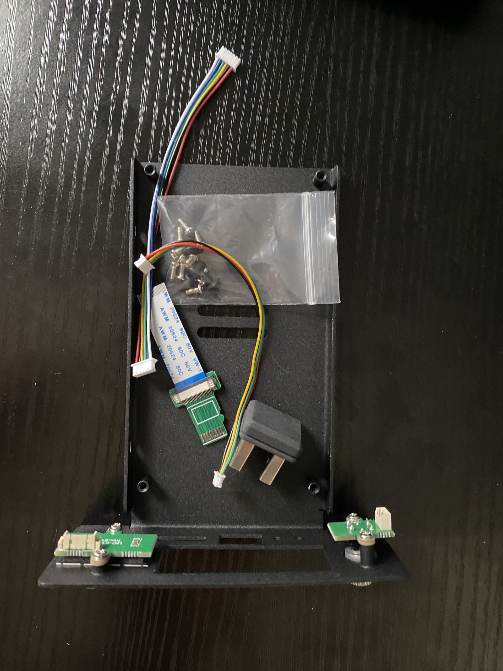
Since I’m using these UCTRONICS trays, I would follow these steps to partially assemble the unit. I’d connect the SSD drive’s SATA connector to the SATA shield card, and screw the SSD card to the side of the tray. Next, I installed the SD adapter into the SATA shield card. I aligned the Raspberry PI4 onto the posts and screwed it on using the threaded standoffs for the PoE+ hat. I inserted the SD adapter into the SD slot of the PI, connected the OLED and power switch cables from the SATA shield card to the front panel. Lastly, I would connect the USB jumper from the SATA shield card to the Raspberry PI4 card for SSD drive connections.
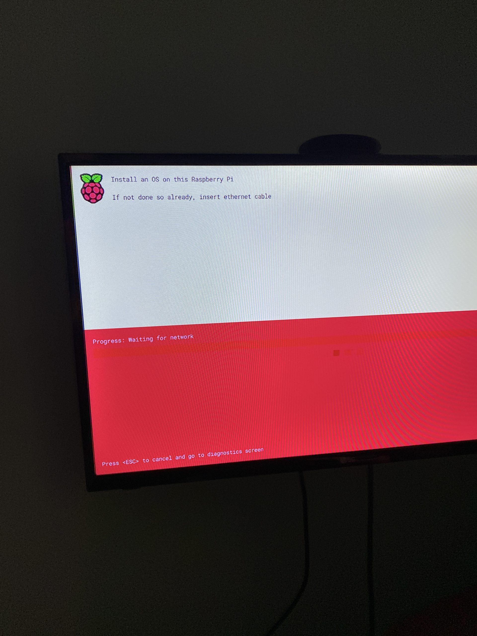
I reused the power supply from my CANA kit, and connected the display and keyboard to the Raspberry PI. I think I could connect power to either the USB-C connector on the PI or on the SATA shield card. An alternative would be to attach the PoE+ hat, but then I’d have to connect ethernet to the PoE+ powered hub, and that was down in the rack, where I didn’t have an HDMI monitor. So I skipped that part, as I was doing this in the study. I connected ethernet cable and powered on the unit. The RPI will display an install screen, where you can press SHIFT key to cause net boot.
This will download the installer image and then restart. You’ll eventually get an installer screen like what the PI imager has on the Mac/PC. It is easiest to use a mouse, but if you don’t have one, you can press the tab button to advance field, and enter to select.
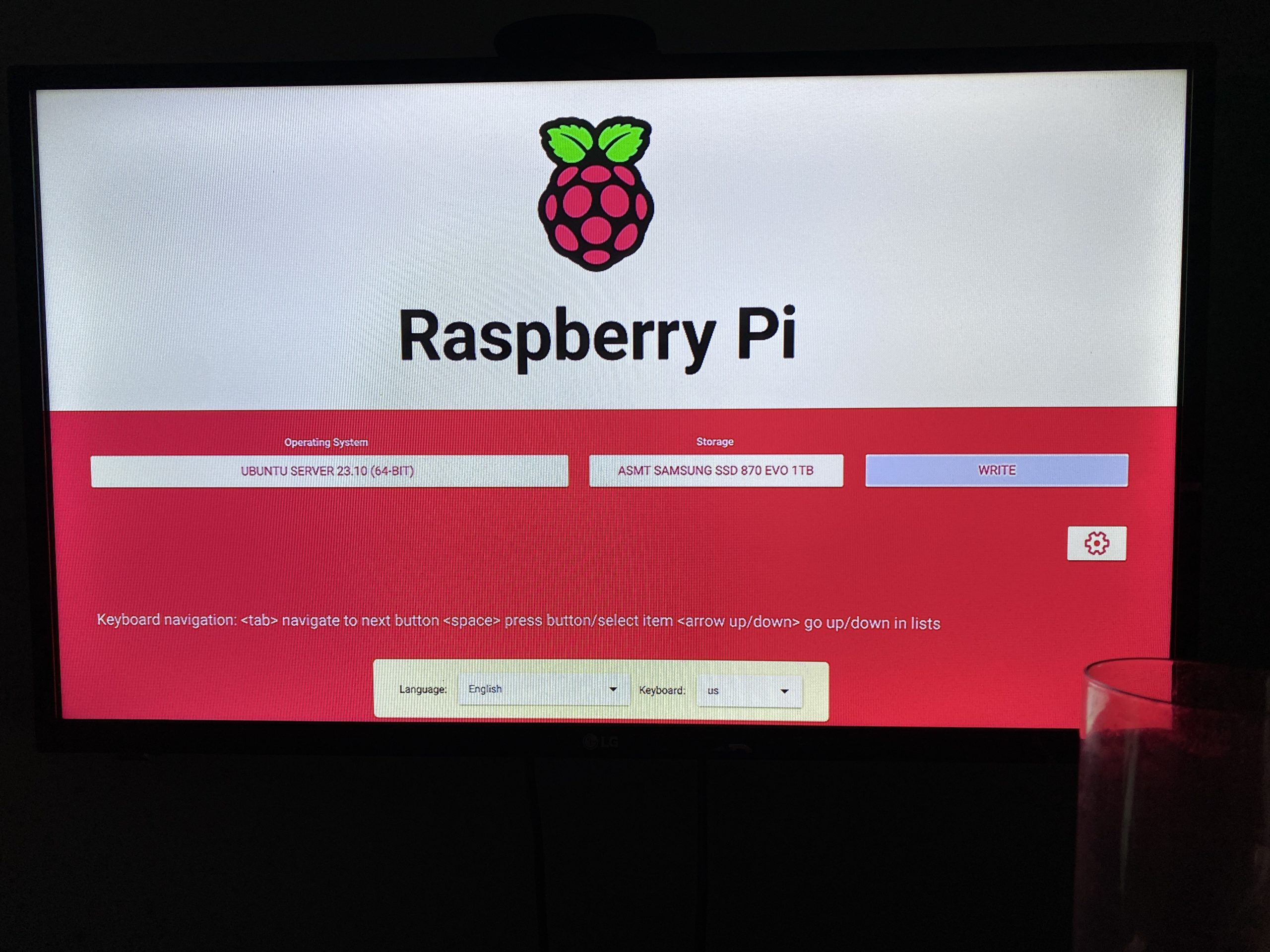
You’ll want to select the model of Raspberry PI (4), select the OS (I used Ubuntu 23.10 64 bit – in the past it was 22.04), and then select the storage device.
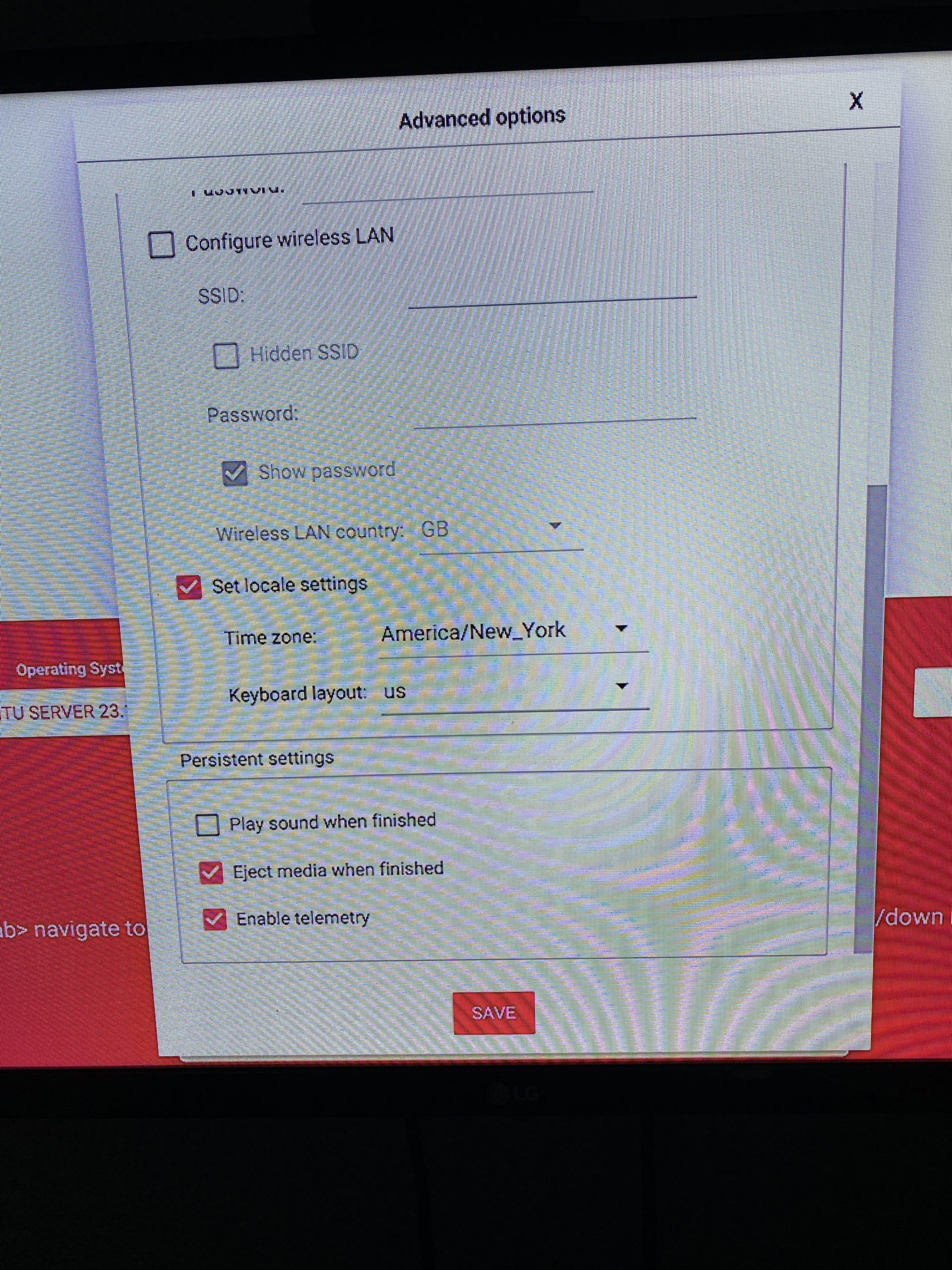
You should see the SSD drive listed (Samsung 1TB drive in my case), and select it. Click the next button, and select to edit the configuration. Enter the host name, enabled SSH with password authentication (for now), and selected a username and simple password (for now). I set the time zone as well. Here is an (older installer) screen shot of some settings.
Lastly, click on SAVE, click on YES to use the changes, and then click on the WRITE button. Again, here is an older screen shot, where there was no PI model button, and the configuration (gear icon) was on the same screen.
Note: I had one case, where the installer would download, and RPI reboot, but the installer image was not coming up and I was seeing kernel panic displayed on the console. I retried, with the SATA drive unplugged, and then plugged it in, after the installer was up and running and I was filling out the storage selection.
While the installer was running, I checked on my router for the hostname, and made a DHCP reservation for the final desired IP I wanted for that system. I also created a HOSTNAME.home DNS entry for this node.
At one point, it rebooted and eventually displayed that cloud init was done. I pressed ENTER and was able to log in. I shut down the system, and then started it back up, so that it would pickup the desired IP address that I setup on my router.
Node Setup
To make setup easier, I created an SSH key on this system, so that I could SSH in from my MacBook and do all the rest from there, without needing the display and keyboard connected. I SSHed into the system, created a key with:
ssh-keygen -t ed25519
and then I copied the public key to all the other nodes and systems so that I can easily get into the system. I also added this new system to the ~/.ssh/config file that I use on other systems, so that I can ssh using the host name. I set the login password to what I really wanted. Make sure that you can ssh into each node, without using a password.
Rather than rely on a DHCP reservation, I changed the /etc/netplan/50-cloud-init.yaml to assign a static IP, set the router IP, and set DNS servers. For the first one, I used my router’s IP as I have it set up to use my Pi-Hole address blocker for primary DNS and a public DNS as a secondary one. This way, later, when I add Pi-Hole to Kubernetes, I can just change the IP on the router and every node will use that new DNS. Optionally, you can add a search clause. I tried “.home” thinking it would then resolve my hosts by hostname, but that isn’t working out. Here is an example 50-cloud-init.yaml:
This was done on each Raspberry PI, with the desired IP address specified, followed by “sudo netplan apply” to update the node. Just be sure to do this via the console, otherwise you’ll loose connection, if done from an ssh session.
Of course, there are several other things that need to be set up on a Raspberry PI, like:
Setting the domain name for the node.
Setting up the OLED display and power switch, since I’m using UCTRONICS tray.
Changing kernel settings.
However, since I’ll be using kubespray to provision the cluster, and kubespray uses ansible, there is the ability to use ansible playbooks to provision all the nodes in a more automated fashion on all nodes. This will be detailed in Part IV, but the next step (Part III) is to do some (optional) partitioning of the SSD drive.
Side Bar
Alternative to netbooting and imaging
On some older units, I went through all sorts of contortions, to install an OS on the SD card using the Raspberry PI imager on my MacBook, booting, updating the rpi-eeprom, setting things up to net boot. There is a bootconfig.txt file that can be used to update the bootload for enabling net boot. I had this entry in there:
BOOT_ORDER=0xf241 SD(1), USB(4), network(2), retry each (f).
Though I’ve seen 0x41 as well. It was really messy. This new loader is much easier.
My SSD drive is not seen at netboot!
I hit a case with some newer SSD drives (a Crucial 2TB BX500 drive), where the drive did not show up in the installer’s list of storage devices to select. To get around this I had to do the following…
I attached the SSD drive to my Mac, using a SATA III adapter, and used the Raspberry PI imager to image the disk (using the same settings as explained above).
Then, I attached the SSD drive to the Raspberry PI’s USB3 port (with the UCTRONICS I installed the drive in the tray, connected to SATA Shield card, and used the provided USB3 jumper. I made sure there was no SD card installed, connected an Ethernet cable and started up the Raspberry PI, making sure it booted from the SSD card.
I have had cases where I had to boot from the SD card running Raspberry PI OS (imaged on a Mac or via net booting the RPI), and run these commands, to update the OS, EEPROM, and bootloader…
I then rebooted, so that the new firmware was activated, and then tried to boot using the SD card and see if the SSD drive was visible (sudo fdisk -l), and then boot without the SD card, hoping it would boot from the SSD drive.
I also tried netbooting to the installer, and instead of choosing an OS, I chose Utility Apps, Bootloader, and picked the option to boot to USB. I wrote that to the SD storage device, it rebooted, and I checked to see if it booted to the SSD. If it did, I would shutdown and restart, without the SD card.
It was a bit of a mess trying to get it working. This happened recently, when I wanted to setup two more PI 4s. One I had to go through these hoops, and the other one worked, after I imaged the SSD on the Mac. I guess the PI4 bootloader should boot from USB, out of the box. For some reason, I hit one that did not.
Currently, I have a few of old tower based Linux servers, running services (VPN, file server, Emby music server, a custom app for monitoring my photovoltaic system, etc). I had started to adapt several of these to run in containers, so that I could move them around, if a system failed, especially since the systems were getting quite old.
In addition, I started to buy some Raspberry PIs so that I had newer technology and hosts that used much less power than my old gear, and I could place these containers on the PIs.
Since I worked with Kubernetes development for several years, before retiring, I decided to build a cluster so I had a way to spread the workload, easily move pods around upon failures, monitor and manage the system, and scale it out as I get more Raspberry PIs.
For the initial design, I have five Raspberry PIs right now, though one is currently hosting a bunch of containers. Plan was to put four of them into service right now, and then once I have my containers migrated over to the cluster, I can add the fifth system. I just got a sixth one for Christmas, so I’ll be adding that in soon.
General Design
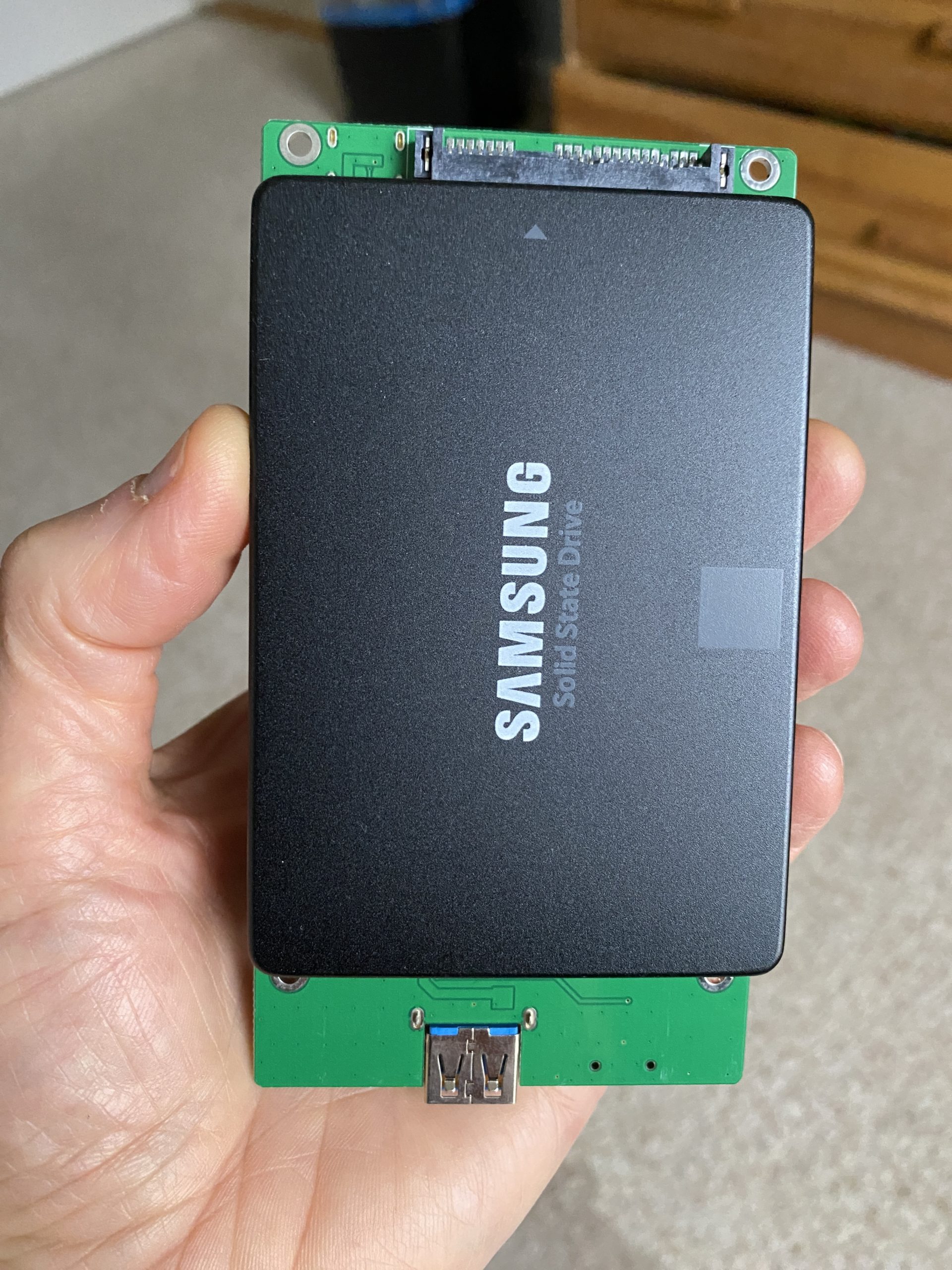
For the hardware, I’m using Raspberry PI 4s with 8 GB RAM (~$85 each), and I have the PoE+ Hats (~$28), so that I can power them off of the PoE based ethernet hub I have (LinkSys LGS116P 8 regular ports, 8 PoE ports ~$120). I purchased a bunch of Samsung 1 TB SSD drives (870 EVO ~$50). Probably should have gotten 2 TB or larger.
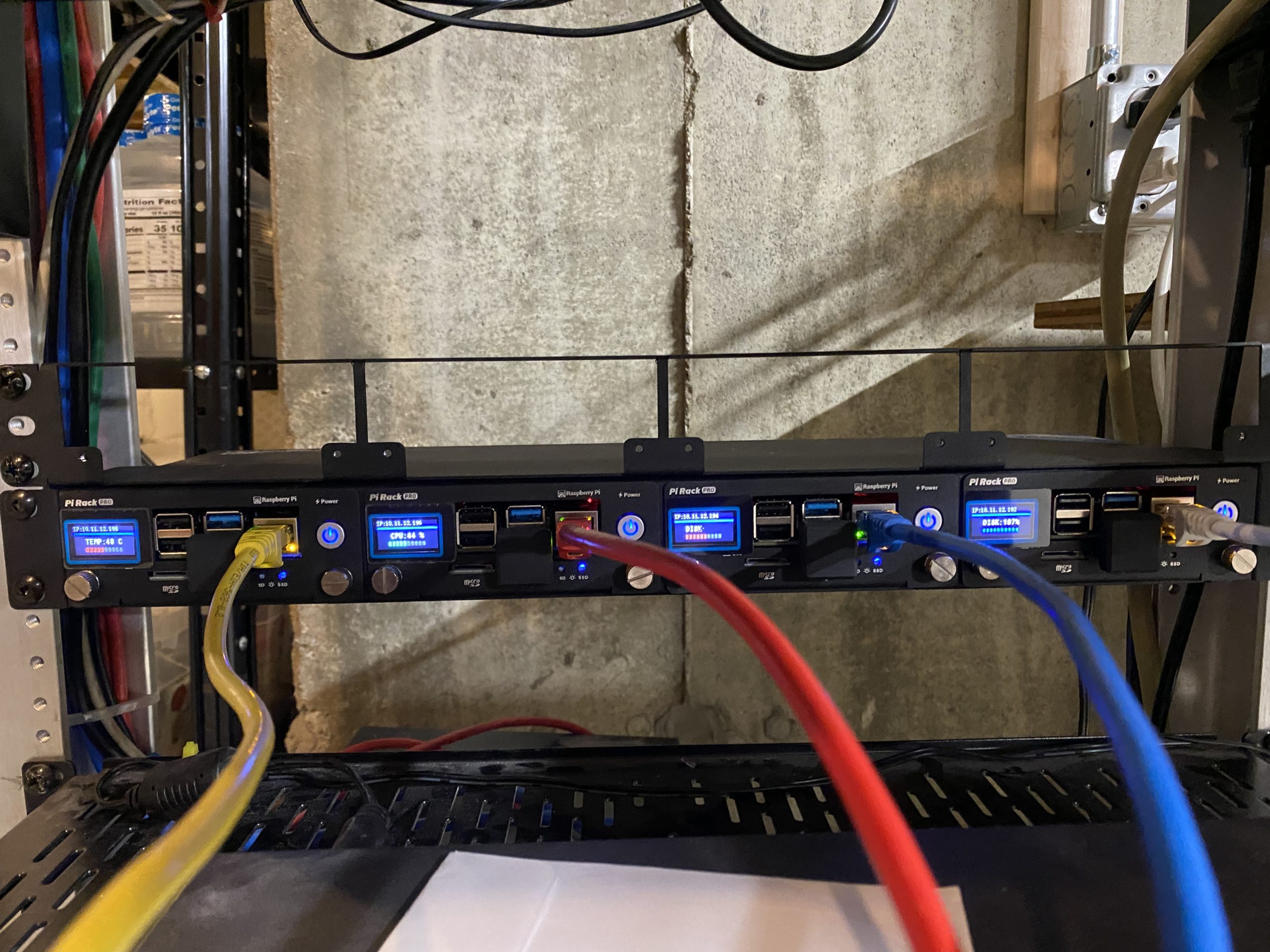
I found a really cool product from UCTRONICS (model B0B6TW81P6 ~$290), which consists of a 1U rack mounted enclosure that holds four Raspberry PI4s, each in a removable tray. There are two fans inside as well. Since I needed one or two more PIs, I also found just a face plate (model RM1U ~ $11) and individual tray units (RM1U-3 ~$76 each). Here is a picture of the enclosure on the bottom, and the face plate on the top.
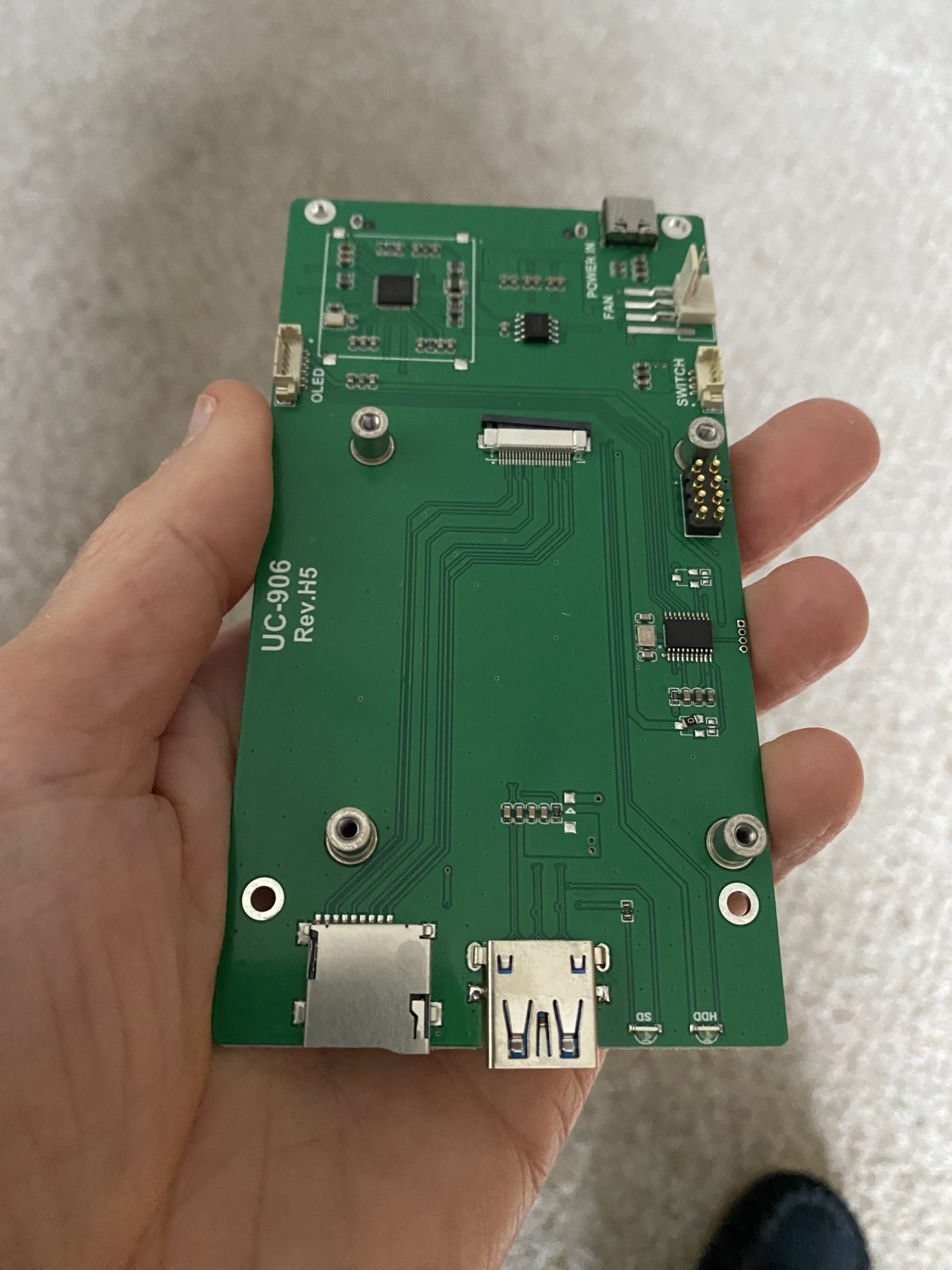
Each of the tray units have a “SATA shield” logic board with SATA connector for the SSD drive on the bottom, a USB connector on the top that can be connected to the USB3 port of the PI using the provided connector and a jumper.
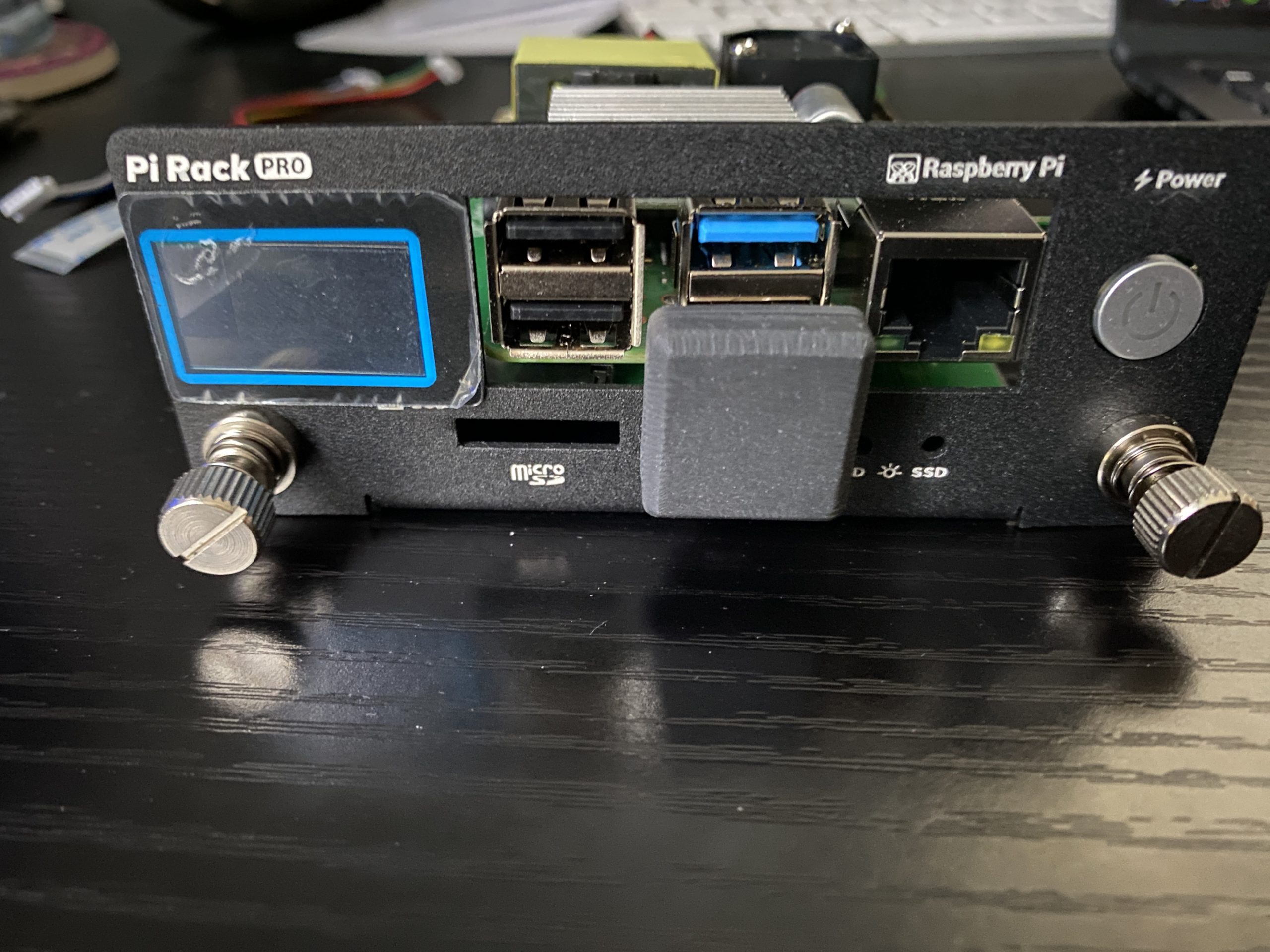
There is a front panel with a LCD that can display IP address, CPU temp, disk usage, and RAM usable (small python app that can be tweaked). There are SD and SSD activity LEDs on the shield card that show, and they provide a jumper cable for the SD card of the PI so that it is accessible from the front panel (via the shield card). Lastly, there is a power switch, so that you can do a clean shutdown.
There is room for the PI’s PoE Hat and a fan connector on the shield card, so that you can attach one of the fans in the enclosure to one of the PIs. The face plate is made out for a Model 4B PI. the enclosure is pricey, but a really great way to place these into a rack, have a SSD drive connected, and be able to cleanly shutdown the units.
The RM1U is not enclosed, and there are no fans, but I wasn’t concerned, as this unit would be in the basement, which is cool year round. I don’t know whether UCTRONICS will make something for the Raspberry PI 5s or how long they will make these rack mounts and enclosures, but it was a nice way for me to bundle things up.
For each of the Raspberry PIs, they will have a fixed IP address and a unique name (versus having node1, node2,…). I chose to have my router reserve IP addresses, outside of the range used for DHCP. Alternately, you could configure each PI with a static IP address.
Part II will discuss how to prepare the PIs for cluster use.
Preliminary support has been added to Lazyjack as of 1.3.5! Now, as of Kubernetes 1.13, the KEP for dual-stack is still under review, and only a few changes have been made to the code, but you can bring up a cluster in dual-stack mode. You will only see one family of IPs for pods displayed via “kubectl get pod”, but if you look on the pods, you will see both IPv4 and IPv6 addresses.
I’ve already updated kubeadm-dind-cluster to support dual-stack for clusters brought up on a single node, using docker-in-docker, but now Lazyjack supports this too, on bare-metal nodes.
The config.yaml file for Lazyjack will have these changes:
A second CIDR can be specified for the management and pod networks, by using the “cidr2” field, under the respective sections. You can specify one family under “cidr” and one under “cidr2”.
The service network CIDR will specify which family is used for the service network. The KEP only supports a single IP family for service networks at this time.
Omit the DNS64 and NAT64 sections, which are not used in dual-stack mode.
The ‘dns64’ and ‘nat64’ operational modes are note specified under the opmodes field any nodes.
Here is an example config that is using IPv6 for the service network:
This proposal will provide IPv4 and IPv6 addresses for all containers (pod network) and nodes (management network), allowing communication with other pods and external resources with either protocol. To simplify this first release will use a single IP family for services, meaning the service network will either be IPv4 or IPv6.
What’s Up?
We’ve started implementing some changes to support dual-stack (as WIP, in some cases, because the KEP is not approved yet). To support that, I’ve modified the kubeadm-dind-cluster provisioning tool (a.k.a k-d-c) so that we can experiment with bringing up a cluster with dual-stack networking, during development.
The changes include setting the CNI configuration files for dual-stack, adding static routes for the Bridge or PTP plugin so that pods can communicate with either IP family across nodes, adjust the KubeAdm configuration file so that the API will use a specific IP family, and does not make use of the DNS64/NAT64 capabilities as both IP families are available on each container.
I’ve verified that we can bring up a cluster in dual-stack mode, with pod to pod (across nodes) and pod to external connectivity using both IPv4 and IPv6. I’ve used IPv4 for the service network, and with PR 70659 (under review as of today), I have verified a cluster with an IPv6 service network.
Granted, there are things that don’t work yet, as much of the KEP needs to be implemented (like service endpoints and pod status API), but it was very satisfying to see a PoC cluster come up.
How To…
To try this out, there are a few preparation steps. First, clone the kubeadm-dind-cluster repo.
cd
git clone https://github.com/kubernetes-sigs/kubeadm-dind-cluster.git dind
Next, clone Kubernetes in a subdirectory underneath k-d-c:
cd ~/dind
git clone https://github.com/kubernetes/kubernetes.git
Within the Kubernetes repo, grab my PR that is out for review (or wait until this is merged):
cd kubernetes
git fetch origin pull/70659/head:pr70659
git checkout pr70659
Now, you can bring up a cluster in dual-stack mode, using the desired service network IP family. You can set the dual stack mode:
export IP_MODE=dual-stack
And since we are customizing the Kubernetes code, we need to tell k-d-c to build a new image:
If you are in a lab, and need to use a company DNS server, you can also set REMOTE_DNS64_V4SERVER.
Now, let’s build a new k-d-c image:
cd ..
build/build-local.sh
cd kubernetes
To use an IPv6 service network, you can just bring up the cluster using the default values:
../dind-cluster.sh up
To use IPv4, you’ll need to first set SERVICE_CIDR to an IPv4 CIDR, before bringing up the cluster. You can use the same value that k-d-c uses for IPv4 only networks, like:
export SERVICE_CIDR="10.96.0.0/12"
Then, just use the same “up” command to bring things up.
In each of these modes, you’ll see either IPv4 or IPv6 addresses, when doing a “kubectl get pods –all-namespaces -o wide” command. The pods will still have both IPv4 and IPv6 addresses, and from the pods, you’ll be able to ping and ping6 to external IPv4 and IPv6 sites, respectively.
Futures…
I haven’t played with external access to the cluster, and obviously there is work to do for the APIs and kube-proxy, along with changes to kubeadm (see the KEP for details).
I’m working on updating my Lazyjack tool that helps with provisioning Kubernetes on bare-metal nodes, so that it too can bring up dual-stack clusters. This will provide feature parity with k-d-c, only using separate physical nodes, instead of Kubernetes running on node containers (using Docker-in-docker) on a single host.
Category: Kubernetes |
Comments Off on Dual-stack Kubernetes with kubeadm-dind-cluster
Several new capabilities have been added to Lazyjack recently:
Supports IPv4 only mode, so clusters can be created with IPv4 addresses.
The kubeadm.conf file generated will use templates that are version specific. This allows easier customizing of the configuration easily. Supports Kuberenetes 1.10-1.13, although experiencing some issues using the alpha 1.13 setup.
Clusters can be configured for insecure mode, where init is not needed, and the config YAML file doesn’t have to be copied over to minions (as it is not updated with a token). This makes it easier to start up a cluster, by just running the prepare and up steps.
Time permitting, I hope to add dual stack capabilities.